
Geometry Configurations Part 4 – Managing nodes and using existing nodes
February 2016: Andreu Tarrida writes this final post in a four-part feature on version control.
December 2015
By Andreu Tarrida
With this new feature, you can code alternative networks within the project that contains the base scenario.
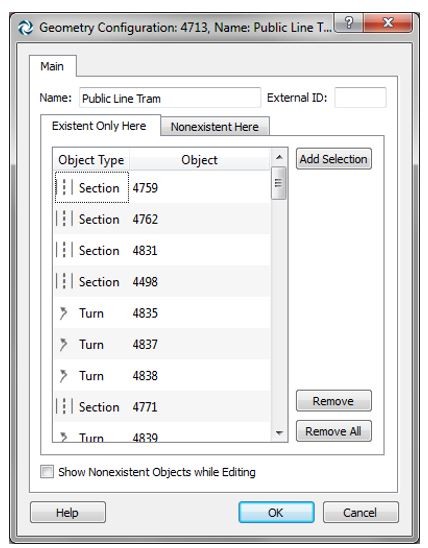
In the geometry configuration object dialog, list the objects that do not exist in the new geometry configuration (“Nonexistent Here” tab) and those that only exist in it (Existent Only Here tab). The rest of objects, which are not included in any of these lists, are common objects between the base and the new geometry.
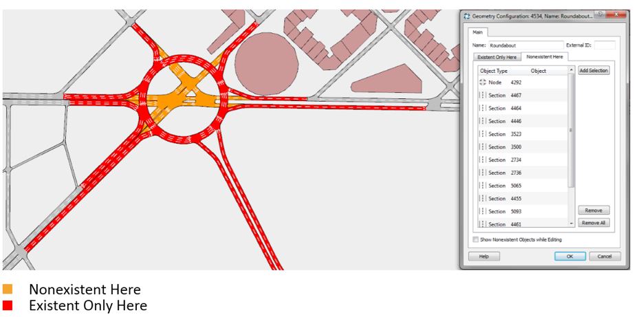
Nodes and turns are the junction between the base geometry and any other geometry configuration. To join a new geometry configuration to the base geometry, try to use the already existent nodes if possible. Do not worry about overlapping new sections and base sections.

Avoid cutting the base geometry to create a new node and join the new geometry, since that could affect the static and dynamic simulations of the base scenario and their corresponding outputs.
1.Create objects for the new geometry configuration.
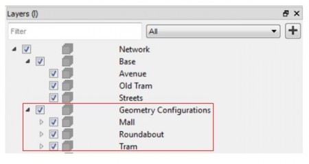
Use an exclusive layer for each geometry configuration and another for the base network.
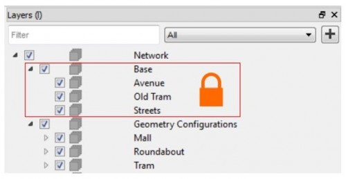
WARNING: When editing the new geometry, avoid accidental modifications to the base network by locking the layers that contain the base geometry objects.
2. List the Nonexistent Here and the Existent Only Here objects in the new Geometry Configuration dialog
3. Associate the geometry configuration(s) with a scenario.
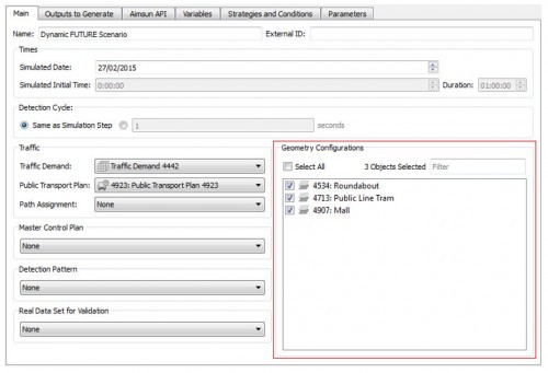
4. Select the scenario in the context drop-down box.
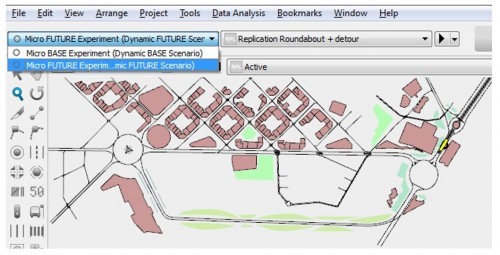
5. Refine the objects and put both geometries together.
Again, you can avoid modifying the base network when editing the new geometry by locking the layers containing base objects. However, great care is needed when editing the nodes that join both geometries, since the base objects will need to be unlocked during this process.

February 2016: Andreu Tarrida writes this final post in a four-part feature on version control.
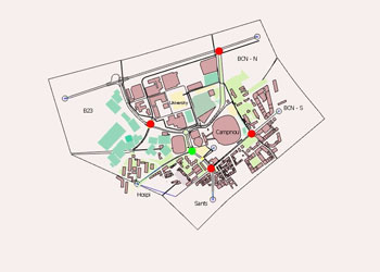
July 2019: Dimitris Triantafyllos shares a pro tip video for keeping track of revised nodes in your project to speed up the editing process.
SHARE
Aimsun Next 24
Aimsun (2024). Aimsun Next 24 User’s Manual, Aimsun Next Version 24.0.0, Barcelona, Spain. Accessed on: April. 16, 2024. [Online].
Available: https://docs.aimsun.com/next/24.0.0/
Aimsun Next 24
@manual {AimsunManual,
title = {Aimsun Next 24 User’s Manual},
author = {Aimsun},
edition = {Aimsun Next 24.0.0},
address = {Barcelona, Spain},
year = {2024. [Online]},
month = {Accessed on: Month, Day, Year},
url = {https://docs.aimsun.com/next/24.0.0},
}
Aimsun Next 24
TY – COMP
T1 – Aimsun Next 24 User’s Manual
A1 – Aimsun
ET – Aimsun Next Version 24.0.0
Y1 – 2024
Y2 – Accessed on: Month, Day, Year
CY – Barcelona, Spain
PB – Aimsun
UR – [In software]. Available:
https://docs.aimsun.com/next/24.0.0/