Select link analysis for schemes

November 2023 — Technical note #82

Tessa Hayman

Product Specialist

When appraising schemes, it can be useful to understand how different schemes may interact with each other. This can help you understand any potential synergy between schemes and identify a subset of scenarios to test with fully detailed modelling. In this technical note, we will show one method for analysing this using the outcomes of the UK Department for Transport (DfT)’s SINAT project.

In Aimsun Next, it is possible to observe all the trips that go through a group of sections, or originate from a set of centroids using the path assignment tab. This is a powerful analysis tool as you can output every trip that is affected by the scheme very quickly or assess sector to sector movements.

The proposed methodology is to use link analysis to understand the trips that go through each scheme and assess the commonality of flows across the network as well as the commonality of the users of the schemes. The commonality of the link flows will be used to assess the synergy between the two schemes – where both schemes may impact on a set of link flows anywhere in the network. The commonality of the trips (using the skim matrices) will be used to assess the alternatives between the two schemes – to assess the impact for alternative routing between the two schemes for the same OD pairs.

As an example, we will apply the above process to analyse the shared impact of two schemes at the locations shown in the image below. The schemes consist in the redesign of two intersections.

To perform this analysis, you need to start with a macroscopic model with a reasonable level of calibration and path assignment. You can use a dynamic model also, but care should be taken if you are assessing an interval as the path assignment tab filters by vehicle generation time rather than the time a vehicle enters/exits a section when using a section filter.

1. Create a grouping for each scheme with the input sections for the scheme. It is important you include only the incoming sections cordoning the area affected by the scheme, i.e. there shouldn’t be traffic that uses more than one section in the grouping, to prevent double-counting. It is not necessary to code the layout of the schemes, you only need to specify the location in the base model.

2. In the path assignment tab, select the grouping for Scheme 1 as sections filter. Note that groupings are listed at the bottom of the drop-down. Then set the logic operator to “Or” to select paths that go through any section in the grouping rather than paths that go through every section (if you included in the grouping only cordon sections as explained above, you should obtain no paths if you set “And”).

3. Click list paths to see all the trips that go through any section in Scheme 1. 

4. Go to actions, output matrices to generate the skim matrices. These are filtered to only include those trips that go through any section in Scheme  1. Click OK to create the matrix objects.

5. Go to the matrices and rename the trips skim matrix with the scheme name. It is the only matrix that you’ll need for this analysis.

6. Click “Link Analysis” to execute the select-link analysis, this will create an output in the view with the total flows from any trip that goes through any section in the scheme.

7. Go to the “Action” drop down and select “Save Link Analysis”. This saves the outputs into columns of the sections so that you can export the data for the scheme interaction analysis.


8. Repeat for scheme 2.  


9.
To export the select-link flows, open the table view, show all the sections, go to “Action”, “Column visibility”. Hide all the columns apart from name and external ID and make the link analysis flow for both schemes visible. This is named Link Analysis Flow – Static Assignment Experiment xxx with the filter that corresponds to the grouping. Go to actions to copy the data and paste it into the analysis spreadsheet. 

10. To turn the skim matrices into lists, select both skim matrices and click matrix comparison. Click actions, copy data, and paste this into the analysis spreadsheet. 


Analysis 

The absolute flow synergy between Scheme 1 and Scheme 2 is the select link flow for Scheme 1 using the links in Scheme 2. In other words, it is the flow that goes through both schemes. Note that the flow for Scheme 1 using the links in Scheme 2 is equal to the flow for Scheme 2 using the links in Scheme 1. 

To calculate this, filter the link analysis flows for Scheme 1 in the spreadsheet to show only the links in Scheme 2 and sum the flow. Note that summing the flow without double-counting is possible thanks to the fact that we have included in each grouping only incoming sections to the scheme area, so that there is no flow that can use more than one section. If this condition cannot be guaranteed, take the highest flow (main representative link) instead of summing. 


Section ID

Total
Relative
flow
synergy


Scheme 1


Via Scheme 2

Scheme 1 total
3096

130

454
3182

48

350
3079

81

303
3086

0.4

0.9


258

1108


23%


Scheme 2


Via Scheme 1

Scheme 2 total
3753

30

564
3288

178

357
3682

51

761


258

1682


15%

In the example network we are analysing, we have 1108 and 1682 vehicles passing through Scheme 1 and Scheme 2 respectively. Of those, 258 vehicles pass through both Scheme 1 and Scheme 2. 

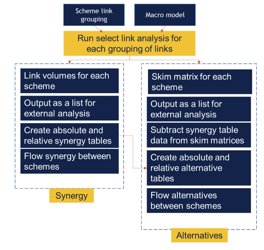
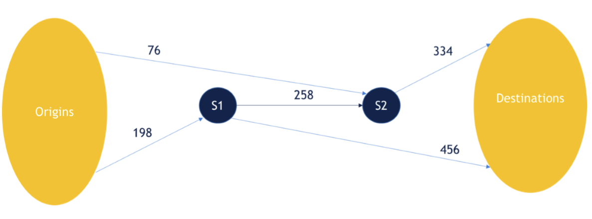
To calculate the relative flow synergy between a pair of schemes, divide the absolute flow synergy for the pair of schemes by the total flow that passes through one of the schemes. Note that the relative flow synergy is not symmetric. 

In the example network we are analysing, the relative flow synergy is 23% and 15% for Scheme 1 and Scheme 2 respectively. 

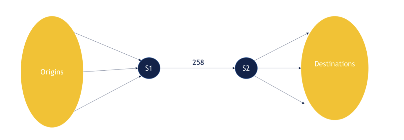
The absolute flow alternative between Scheme 1 and Scheme 2 is the sum of the of trips in scheme 2 where there are trips from same OD pair in Scheme 1.
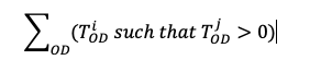
Where  is the number of trips from origin O to destination D that goes through scheme i

This records both the trips split between parallel schemes as well as those in consecutive schemes (schemes in synergy). Therefore, to separate the flow alternatives from the flow synergies, you must subtract the absolute synergy flow. 

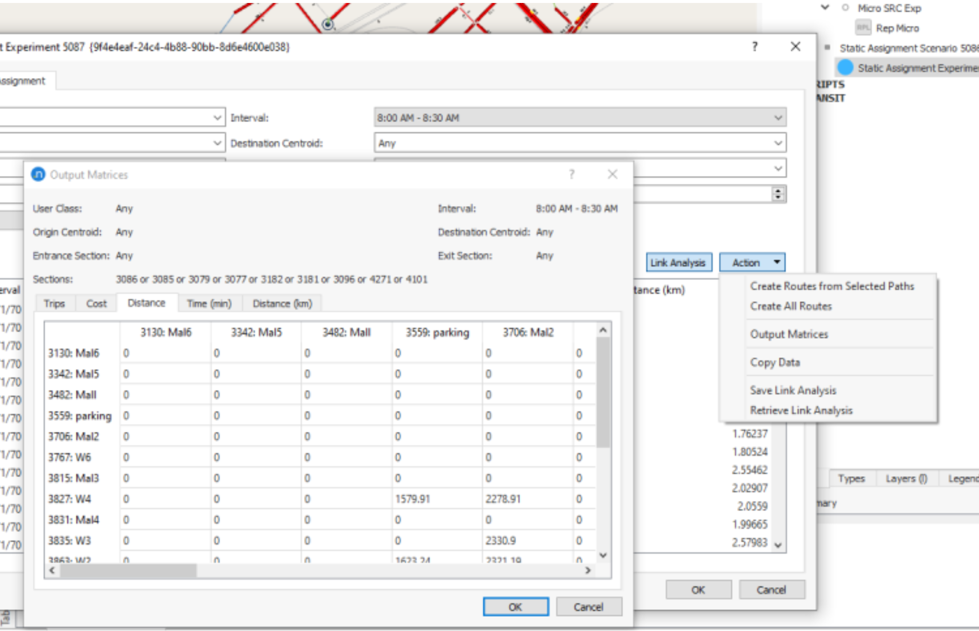
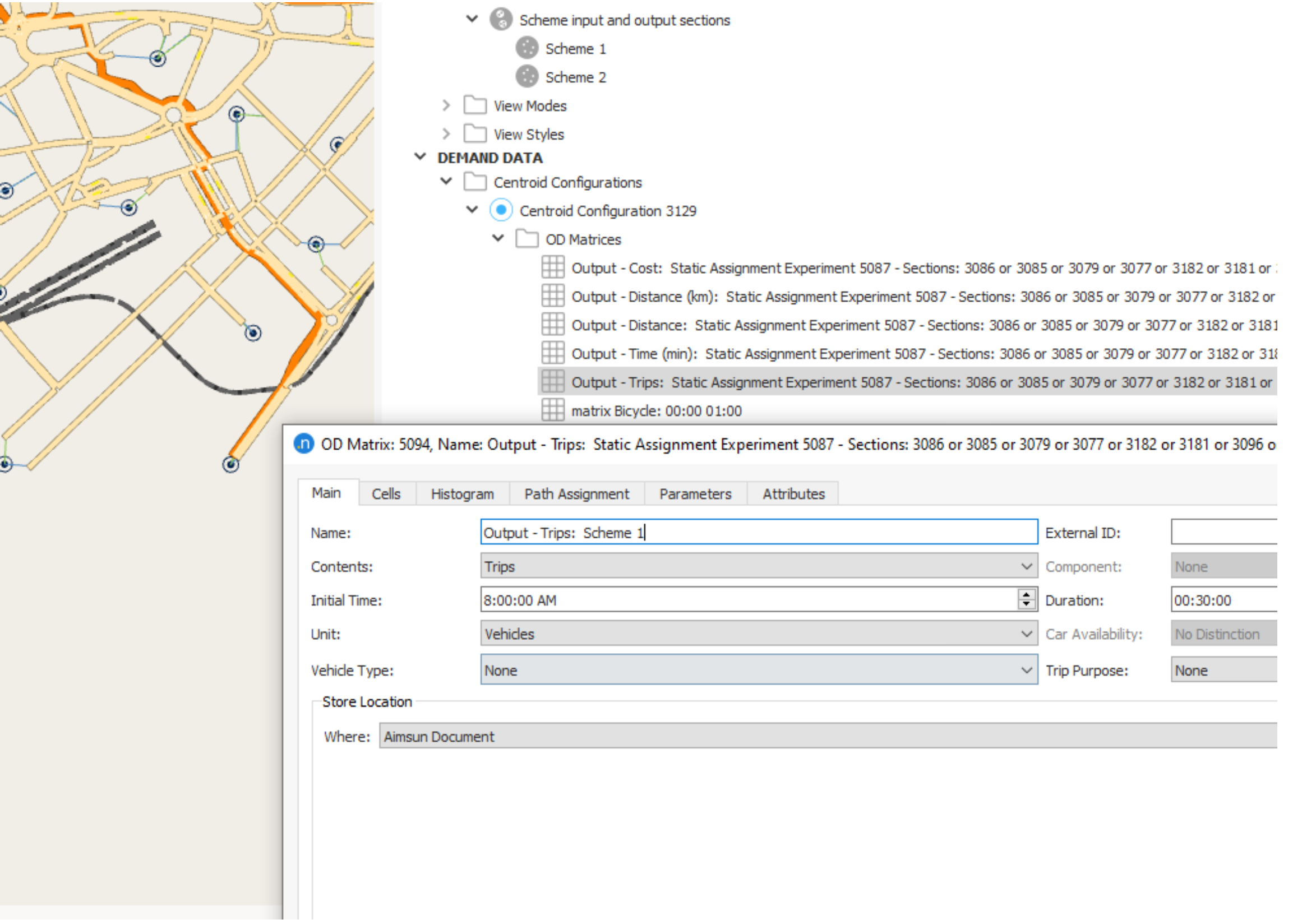
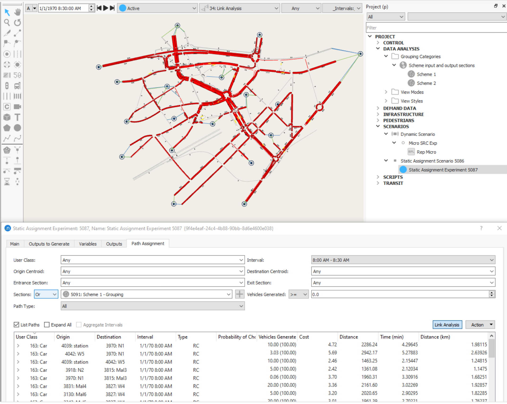
To perform this analysis, we use the trip skim matrices produced with the link analysis. 


Synergy                    Total

Alternative


Scheme 1      


Via Scheme 2

Scheme 1 total


258

1108
Trips that could go
through Scheme 1 and/or Scheme 2
Without trips that go
through Scheme 1 AND Scheme 2

Relative
334
76
7%
Scheme 2      
Via Scheme 1

Scheme 2 total
258

1682
198
198
12%

In the example network we are analysing, there are 334 trips which pass through Scheme 2 which share OD pairs with trips that go through Scheme 1. That is there are 334 trips that potentially could also go through Scheme 1 if the route choice was different. There are 456 trips which pass through Scheme 1 which share OD pairs with trips that go through Scheme 2.  

To remove the effect of synergy, the absolute flow synergy for each scheme should be subtracted from the flow alternative which gives 76 and 198 trips for Scheme 1 and Scheme 2 respectively. 

The relative flow alternative between a pair of schemes, divide the absolute flow alternative for the pair of schemes by the total flow that passes through one of the schemes. 

In the example network we are analysing, the relative flow alternative is 7% and 12% for Scheme 1 and Scheme 2 respectively. 

By comparing multiple schemes against each other using this method across a network, modellers can decide which schemes should be tested together in a scenario to better assess their impact. 

If there are a substantial number of schemes, this analysis process can be undertaken using scripting within Aimsun Next.  

More technical notes

  • Got a question? Get in touch.

    We are here to help!

SHARE

Cite Aimsun Next

Aimsun Next 24

Aimsun (2024). Aimsun Next 24 User’s Manual, Aimsun Next Version 24.0.0, Barcelona, Spain. Accessed on: April. 16, 2024. [Online].

Available: https://docs.aimsun.com/next/24.0.0/

Aimsun Next 24

@manual {AimsunManual,
title = {Aimsun Next 24 User’s Manual},
author = {Aimsun},
edition = {Aimsun Next 24.0.0},
address = {Barcelona, Spain},
year = {2024. [Online]},
month = {Accessed on: Month, Day, Year},
url = {https://docs.aimsun.com/next/24.0.0},
}​​​​​​​​​​​​​​​

Aimsun Next 24

TY – COMP
T1 – Aimsun Next 24 User’s Manual
A1 – Aimsun
ET – Aimsun Next Version 24.0.0
Y1 – 2024
Y2 – Accessed on: Month, Day, Year
CY – Barcelona, Spain
PB – Aimsun
UR – [In software]. Available:
https://docs.aimsun.com/next/24.0.0/