How to Connect Siemens UTC SCOOT to Aimsun Next 20

Technical Note #56
February 2021

By Dimitris Triantafyllos

Did you know that an Aimsun Next junction (node) can be linked to an external controller, such as the Siemens UTC System with SCOOT?

The aim of this technical note is to show how the dynamic signal control system, Siemens UTC System with SCOOT (hereafter called ‘SCOOT’), connects with Aimsun Next. In doing so, it provides a link that enables the SCOOT algorithm to be incorporated into a simulation and for signals to be set in response to conditions in the traffic network.


The effect in the simulation is that signals change at the same times, or in response to traffic conditions, as they do on the road.


Please note the following important requirements:


  • A license for both Aimsun Next and SCOOT + Adaptative control interfaces.
  • You (or the modeler if different) must have access to the SCOOT Database.
  • Software configurations should be ready to run the current activity. All the required UTC software should be installed (UTC Backup and Restore, Xming, and XLaunch).
  • System settings (the required folder structure and a new Windows user account) should be in place. The tasks in these last two points will require the assistance of a SCOOT expert.

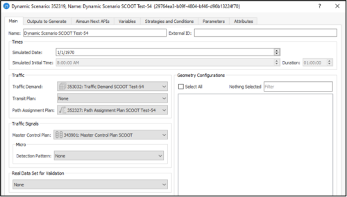
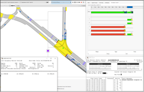
The following step-by-step guide (12 steps) explains how to connect a junction in Aimsun Next to SCOOT in a Windows OS environment.


  1. Press the Start key and search for “UTC Backup and Restore”.
     
  2. Enter your SCOOT Username and Password. These credentials will be provided by the SCOOT expert. The UTC Backup and Restore dialog is displayed.
     
  3. Click the Restore tab and then:
    1. From the drop-down menu (1) Select a backup source, select UTC checkpoint area.
    2. Click Start Restore to restore UTC detector and signals data from the UTC database.


How to Connect Siemens UTC SCOOT to Aimsun Next 20
 
  1. Press the Start key and search for “UTC Machine Configuration”.
     
  2. Select System Startup > Start UTC System > OK.
 
  1. Press the Start key and search for “XLaunch”.
     
  2. Start the XLaunch application and, in the setting window, keep the preselected selections.


How to Connect Siemens UTC SCOOT to Aimsun Next 20
 
How to Connect Siemens UTC SCOOT to Aimsun Next 20
 
  1. Right-click on the Taskbar icon Xming and select UTC Login.


How to Connect Siemens UTC SCOOT to Aimsun Next 20
 
  1. The UTC Login dialog will be displayed. Reenter your SCOOT Username and Password, and click OK.


How to Connect Siemens UTC SCOOT to Aimsun Next 20
 

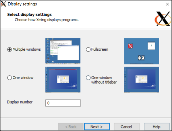
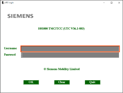
The following dialogs will be displayed.


How to Connect Siemens UTC SCOOT to Aimsun Next 20
 

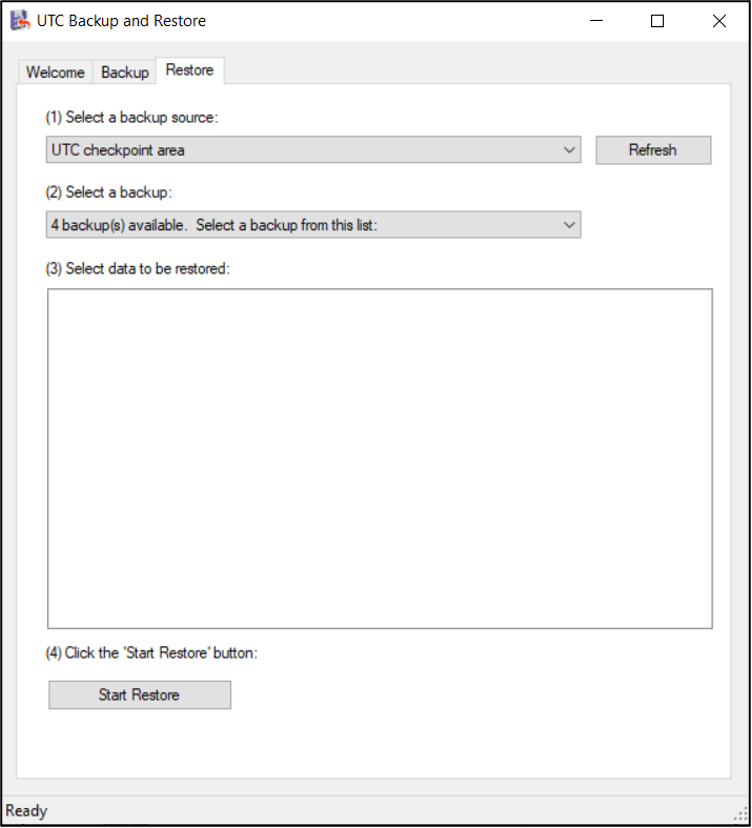
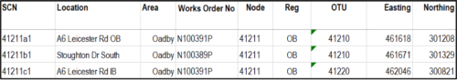
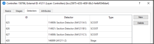
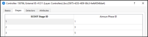
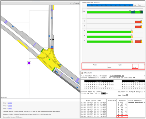
In our example we will connect specific SCOOT junctions to an ‘external’ application (Aimsun Next) and view messages while the simulation is running. To do this, we need to set the junction sites on the SCOOT control.


  1. In the field Enter a UTC command, type SCOO R* and click Accept.


How to Connect Siemens UTC SCOOT to Aimsun Next 20
 
  1. To display the most important messages in the Output Messages dialog, enter the following commands:
    • MESS D80 H01000
    • MESS D81 H01000


How to Connect Siemens UTC SCOOT to Aimsun Next 20
 
 
  1. (Optional) You can also enter the following commands if required.
    • To monitor the control plan of a specific junction (junction IDs begin with J): DIPM J41211
    • To restart SCOOT if it doesn’t respond:
      XSCO R* (removes all regions from SCOOT)
      REIN
      SCOO R*
    • To monitor the status of a detector: LMON N41211A
    • To check the SCOOT configuration: LVAL N41211A
 

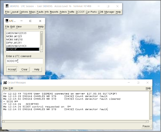
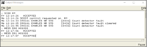
By this stage, SCOOT should be up and running and ready to connect with Aimsun Next.

Successful connection between SCOOT and Aimsun Next depends on the following exchange of information:


·      From SCOOT to Aimsun: Stage information

·      From Aimsun Next to SCOOT: Detector information (Presence and Occupancy parameters must be selected).


To guarantee a connection between SCOOT and Aimsun Next, SCOOT objects must have a one-to-one correspondence with Aimsun objects. This means that an adaptive signal-control system requires an Aimsun Next controller object at each junction to manage the link between the external system and the Aimsun Next network.


You can use Aimsun Next controllers to create and edit the links between junctions, their associated signal stages, and traffic detectors with their corresponding objects in the SCOOT system.


An exchange of information between SCOOT and Aimsun Next (synchronisation tokens, detector measures, and stages) takes place every second, as required by SCOOT. The detection cycle (Dynamic Scenario > Outputs to Generate tab) should therefore be set to 1 second.


Connect Aimsun Next to SCOOT

To enable the connection with SCOOT:


1. Open the ANG file in Aimsun Next.


2. Identify which SCOOT junctions are included in the study area and locate those in the Aimsun Next network. In most cases, the SCOOT junction location and ID are provided by the traffic management center (TMC) or the City Authorization of the area. Usually, SCOOT junctions are marked on a map (PDF file or image file).We will use a SCOOT junction with the ID N41211 to demonstrate the step-by-step workflow required to connect SCOOT to Aimsun Next.


3. Open the relevant node in the network and set the External ID as N41211.

4. Set the signal groups in the node object.


a. First, open the SCOOT specifications (PDF from TMC or an external source). Scroll down, until you find the ‘Phase Type and Conditions’ section and use the ‘Title’ information to identify the signal group movements of each junction. For example, ‘Phase’ A, ‘Title’ A6 Leicester RD – TO CITY (INB) means that Phase A (which is movement A in Aimsun terms) is assigned to the A6 Leicester Road heading toward the city center.

b. Click the Signal Groups tab and map the SCOOT phases (A–J in the screenshot above) to Aimsun Next signal group names (A–J in the screenshot below).

5. Set the signal phases in the relevant Aimsun Next control plan.


a. In the same SCOOT specification document, find the ‘Phases in Stages’ section. This is the SCOOT phasing/staging information that is required to assign the signal groups into phases in Aimsun Next’s control plan object.

In the example above:

  • Stage 1 contains A, B, E, F
  • Stage 2 contains C, D, G, H
  • Stage 4 contains I
  • Stage 5 contains J.


b. Open the control plan and complete the following steps:


i. Set the Control Type to External.

ii. On the Timing subtab, add phases and interphases.

iii. Assign signal groups to the corresponding phases. The durations of phase and interphase should be set to reflect the real-world backup control plan. This is so that, if the connection between SCOOT and Aimsun Next is lost, the real-world backup control plan will be activated.

iv. Create a new master control plan and include the recently created SCOOT external control plan.

6. From SCOOT, export the SCOOT detector information and then import (manually or by using Python scripts the SCOOT detector loop data into Aimsun Next. In the following example, the detector data was exported from the SCOOT Database in CSV format.

In the first column there are three SCOOT detectors associated with junction N41211: 41211A1, 41211B1, and 41211C1.


7. Check the SCOOT specifications to see whether any SCOOT stages are demand-dependent (meaning stages that are actuated only when there is demand present). If any demand-dependent stages are found, you should install a stage detector in the corresponding turn related to that stage.


In the following example, the ‘UTC Demand Dependent Forces’ section of the SCOOT specifications contains information about demand-dependent stages. Based on the screenshot below, Stage 2 (which is sometimes also described as Stage B in the SCOOT documents) with phases C, D, G, and H is demand-dependent.

8. Sometimes, SCOOT loop drawings (PDF) are available. You can use these to better position the SCOOT and stage detectors in the Aimsun Next network. In our example, the following drawing helped us to locate SCOOT detectors 41211A1 (outbound from the city center) and 41211C1 (inbound to the city center).

9. Add four new detectors to the Aimsun Next network position them as indicated in the screenshot below.

10. Enter External IDs for each detector, as illustrated:


  • N41211A1
  • N41211B1
  • N41211C1
  • J41211-2 (demand-dependent).


Microsimulation Configuration File

A file named microsim_config.cnf is required to serve as an interface between Aimsun Next objects and SCOOT objects. The file maps SCOOT junctions, detectors, and stage detector IDs to the corresponding objects in the Aimsun Next controller.


For this to work, it is essential that you have set the same external IDs for the junction and its detectors in both Aimsun Next and SCOOT, as explained in the previous steps.


To create the cnf file:


a. Open a new text document.


b. Rename the file cnf.


c. Add the SCOOT junction (J41211), detectors (N41211A1, N41211B1, N41211C1), and the stage detector (J41211-2) to the file.


d. Send this file to the SCOOT expert so they can process it and generate new IDs for these objects.


e. The expert will produce a new version of the file cnf, with the new IDs (201, 420, 625, 626, 627) alongside the previous junction and detector IDs.


f. Save the cnf file in this location:


C:\ProgramData\Siemens Mobility Limited\UTC\movable\sys\current\tcca.


The file format for junctions, stage detectors, and stage detectors is as follows:


    • [Junction ID][space][ID][space]x
    • [Stage Detector ID][space][ID][space]x
    • [SCOOT Detector ID][space][ID][space]x


In our example, the contents of the microsim_config.cnf file will therefore be:


    • J41211 201 x
    • J41211-2 420 x
    • N41211A1 625 x
    • N41211B1 626 x
    • N41211C1 627 x


11. Add a new controller to the Aimsun Next network and set the following parameters:


  • Type: Siemens UTC System
  • Tick Enabled
  • External ID: 41211
  • Intersection ID: 201
  • Port: 2809
  • IP: 127.0.0.1.


Port and IP values must match those in SCOOT. If in doubt, check with your SCOOT expert.

12. Click the Detectors tab and set the following IDs in the ID column: 625, 626, 627, 420. Also, set the Type of detector to either SCOOT or Stage.

13. Click the Stages tab and map the SCOOT stage IDs (found in the SCOOT specifications ‘Phases in Stages’ section) with the Aimsun phase IDs (found in the control plan object) as illustrated below.

14. Open the dynamic scenario and for Master Control Plan, select the SCOOT plan.

15. Run the replication associated with the scenario and experiment, and check for the following messages in the Log window:


“Initializing CORBA: …”

“Connected to Siemens UTC System.”

16. To verify that the current active phase in Aimsun Next is the one that SCOOT sends to Aimsun Next, double-click on the relevant node in the network and click the Simulation Control tab while the simulation is running. Watch the subsequent actuation of the phases in the control plan.


17. Switch to the DIPM window by entering the command DIPM J41211 in the SCOOT application.

The screenshot below shows that 22 seconds ago SCOOT sent an order to activate state A to Aimsun Next. In Aimsun Next, phase 1 has been active for 21.6 seconds, as indicated in the Simulation Control tab. This means that the connection is working correctly.

18. To live changes to the status of a detector (in this example N41211B), enter the command LMON N41211B1 in SCOOTS to open the LMON window for the specific detector. Each digit – either 0 or 1 – corresponds to a no-presence (=0) or presence (=1) measurement, with a frequency of 0.25 seconds. In the following example where 111 is highlighted, the vehicle that just crossed detector N41211B1 was measured as being present for 0.75 seconds.

Several vehicles have crossed detector N41211B1. Also, most of the vehicles have already crossed the stage detector J41211-2. Because stage B (SCOOT) and phase 3 (Aimsun Next) are demand-dependent, we expect it to be actuated in a few seconds based on the SCOOT logic. You can see the activation in both SCOOT and Aimsun Next applications.

Tip: The SCOOT interface can be configured to produce debugging information. You can select this option in the dynamic scenario. Open the scenario and click the Output to Generate tab > Controllers tab and tick the option Generate Debug Files. When this option is selected, Aimsun Next will generate log files which are stored in the same folder as the ANG file.

More technical notes

  • Got a question? Get in touch.

    We are here to help!

SHARE

Cite Aimsun Next


Aimsun Next 23

Aimsun (2023). Aimsun Next 23 User's Manual, Aimsun Next Version 23.0.0, Barcelona, Spain. Accessed on: July. 19, 2023. [Online].
Available: https://docs.aimsun.com/next/23.0.0/


Aimsun Next 20.0.5

Aimsun (2021). Aimsun Next 20.0.5 User's Manual, Aimsun Next Version 20.0.3, Barcelona, Spain. Accessed on: May. 1, 2021. [In software].
Available: qthelp://aimsun.com.aimsun.20.0/doc/UsersManual/Intro.html
 

Aimsun Next 23

@manual {​​​​​​​​AimsunManual,

title = {​​​​​​​​Aimsun Next 23 User's Manual}​​​​​,
author = {​​​​​​​​Aimsun}​​​​​​​​,
edition =  {​​​​​​​​​​​​​​​Aimsun Next 23.0.0}​​​​​​​​​​​​​​​,
address = {​​​​​​​​​​​​​​​Barcelona, Spain}​​​​​​​​​​​​​​​,
year  = {​​​​​​​​​​​​​​​2023. [Online]}​​​​​​​​​​​​​​​,
month = {​​​​​​​​​​​​​​​Accessed on: Month, Day, Year}​​​​​​​​​​​​​​​,
url = {​​​​​​​​​​​​​​​https://docs.aimsun.com/next/23.0.0/}​​​​​​​​​​​​​​​,
}​​​​​​​​​​​​​​​


Aimsun Next 20.0.5

@manual {​​​​​​​​AimsunManual,

title = {​​​​​​​​Aimsun Next 20.0.5 User's Manual}​​​​​​​​,
author = {​​​​​​​​Aimsun}​​​​​​​​,
edition =  {​​​​​​​​​​​​​​​Aimsun Next 20.0.5}​​​​​​​​​​​​​​​,
address = {​​​​​​​​​​​​​​​Barcelona, Spain}​​​​​​​​​​​​​​​,
year  = {​​​​​​​​​​​​​​​2021. [In software]}​​​​​​​​​​​​​​​,
month = {​​​​​​​​​​​​​​​Accessed on: Month, Day, Year}​​​​​​​​​​​​​​​,
url = {​​​​​​​​​​​​​​​qthelp://aimsun.com.aimsun.20.0/doc/UsersManual/Intro.html}​​​​​​​​​​​​​​​,
}​​​​​​​​​​​​​​​

Aimsun Next 23

TY  - COMP
T1  - Aimsun Next 23 User's Manual
A1  - Aimsun
ET - Aimsun Next Version 23.0.0
Y1  - 2023
Y2 - Accessed on: Month, Day, Year
CY  - Barcelona, Spain
PB  - Aimsun
UR  - [In software]. Available: https://docs.aimsun.com/next/23.0.0/


Aimsun Next 20.0.5

TY  - COMP
T1  - Aimsun Next 20.0.5 User's Manual
A1  - Aimsun
ET - Aimsun Next Version 20.0.5
Y1  - 2021
Y2 - Accessed on: Month, Day, Year
CY  - Barcelona, Spain
PB  - Aimsun
UR  - [In software]. Available: qthelp://aimsun.com.aimsun.20.0/doc/UsersManual/Intro.html